CAPSTONE LESSON
www.iqytechnicalcollege.com/CapstoneLesson.pdf

www.iqytechnicalcollege.com/CapstoneLesson.htm

UEENEEG105A
http://www.highlightcomputer.com/electricaltrade2021.htm#G105
UEEEL0039
1.Prepare to design, install,
inspect and test an electrical installation
UEEEL0039
5. Visually
inspect and conduct safety testing on electrical installation
VISUAL
INSPECTION
|
Portable Electrical Equipment |
Yes |
No |
|
1. Is there damage (apart from light scuffing)
to the cable sheath? |
|
|
|
2. Is the plug damaged (eg.
the casing cracked or pins bent)? |
|
|
|
3. Are there inadequate joints, including
taped joints, in the cable? |
|
|
|
4. Is the coloured
insulation of the internal cable cores showing where they enter the plug? |
|
|
|
5. Does the appliance appear to have been
subjected to conditions for which it is not suitable (eg.
is it wet or excessively contaminated)? |
|
|
|
6. Is there damage to the external casing
of the equipment or are there loose screws or parts etc? |
|
|
|
7. Is there evidence of overheating (eg. burn marks or discoloration)? |
|
|
|
8. Is the main on/off switch damaged, does
it operate incorrectly? |
|
|
|
Notes: |
||
An answer “Yes” to any of the above
indicates that the appliance is potentially dangerous and must be taken out of
use.
|
General
Electrical Inspection: Visual inspection of electrical equipment may include
the following: |
Yes |
No |
|
1. Flexible cords in good condition ie look for cuts, abrasion or damage |
|
|
|
2. External components or casing are not damaged (these
may form part of the insulation) |
|
|
|
3. Power and extension cords anchored and separated from
other hazards such as liquids, mechanical action or
traffic areas. |
|
|
|
4. Covers, guards, controls, alarms
or mechanical safety features are in good condition |
|
|
|
5. Power outlets and power boards are not overloaded. |
|
|
|
6. Cords are kept away from traffic areas. |
|
|
|
7. Electric cords and wiring are not kept under carpets
where they are subject to wear and tear |
|
|
|
8. Electric cords and wiring are not run through windows
or doorways where they are subject to abrasion |
|
|
|
9. Double adapters are not used (power-boards should be
used) |
|
|
|
10. Bar radiators and para-flood lamps are not used for
heating purposes |
|
|
|
11. Appropriate electrical equipment are
used in wet areas such as around sinks and in toilets |
|
|
|
12. Only designated electrical appliances, equipment, or
extension cords are used in areas which contain dangerous or hazardous
materials (flammable, explosive, or corrosive) |
|
|
|
Notes: |
||
Continuity of Main Earth and
Bonds
Which Earth Continuity Test
·
·
Which Earth
Continuity Test?
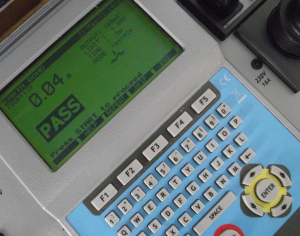
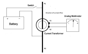
The
earth continuity test is a designed to test the resistance of the protective
earth of an appliance and/or the supply lead. It is measured between any
accessible earthed parts and the earth pin of the plug.
The
test is based on the principles of Ohm’s Law.
By
applying a known voltage and current, the resistance can be calculated using
the formula Voltage ÷ Amps = Resistance ( Ω ).
When
performing the earth continuity test you have three options for the test
current you apply.
- 12 V
maximum, test current in the range 100 to 200 mA; commonly known as “screen test”
- 12 V
maximum, test current of 10 A ( rarely used )
- 12 V
maximum, test current of 1.5 times the rated current of the appliance or
25 A, whichever is the greater; commonly known as
a “bond test”
Most
portable appliance testers (PATs), including multimeters,
should be able to perform the screen test. The screen test is useful for detecting poor
connections of the earth conductor to either the chassis or the earth pin of
the plug, commonly due to a loose connection or corrosion; the low current
being applied makes it fairly sensitive to increases
in resistance.
The bond test is useful for
detecting defects such as breaks in the strands of the earth conductor or
connections that can’t handle the maximum potential current load that could go
through the earth conductor; the higher current being applied would result in
high resistance reading.
When
there is resistance to the current flow the energy is converted into heat. The
heat may be great enough to cause the filaments to melt. Here are two examples
to demonstrate how you could have a situation where
performing one type of test could produce a pass and the other test would
produce a fail.
Example 1 The earth connection to the chassis of the appliance is corroded.
This could inhibit the flow of the low test current
used with the screen test and result in high resistance readings. However the test current used in the bond test is
significantly higher and it could “ram through” like a Mac truck with little
resistance. In this case, the screen test would be the best choice as it would
detect the defect.
Example 2 The connection to the earth pin is held in place by only a
few strands. The screen test would produce a pass as there are enough strands
to allow the current to flow with little resistance, however there are not
enough strands for the higher test current of the bond test to flow unimpeded.
This resistance could cause the strands to get so hot they melt and produce a
very high resistance reading. In this case, the bond test would be the best
choice.
Summary As you can see from these two common examples neither test
can detect all possible earthing defects, each test has their own pros and
cons.
So which should you use? Unfortunately
there is no right or wrong answer. You may in fact want to perform both. Don’t
be too concerned about performing the bond test on IT equipment. I have done
thousands of these without any damage occurring to the appliance(s) and believe
it doesn’t pose a risk to the appliance provided you do it correctly.
Further
reading: Standard AS/NZS 3760 Appendix
D
Learn How To Test and Tag – In-Service
Inspection and Safety Inspection of Electrical Appliances And Cord Sets to
AS/NZS 3760 Click here>> Test Tag Courses
For all protective conductors,
including main and supplementary bonding conductors, electricians must
perform a continuity test using a low-reading ohmmeter. For main equipotential
bonding, there is no single fixed value of resistance above which the conductor
would be deemed unsuitable. [See European terminology list at end of
article]
[Introduction photograph.
Continuity of protective conductors (Photo credit: tradeskills4u.co.uk)]
Each measured value, if
indeed it is measurable for very short lengths, should be compared with the
relevant value for a particular conductor length and size. Such values are
shown in Table 1.
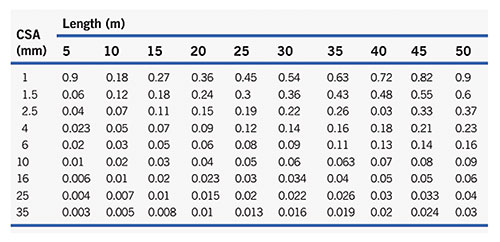 Table
1. Resistance (O) of Copper Conductors at 20°C
Table
1. Resistance (O) of Copper Conductors at 20°C
Where a supplementary
protective bonding conductor has been installed between simultaneously
accessible exposed and extraneous conductive parts the resistance of the
conductor R must be equal to or less than 50/ Ia.
So, R ≤ 50/Ia, where 50 is the voltage, above which exposed metalwork
should not rise and Ia is the minimum current,
causing operation of the circuit protective device within
5s. For
example, suppose a 45 A BS 3036 fuse
protects a cooker circuit, the disconnection time for the circuit cannot be
met, and so a supplementary bonding conductor has been installed between the
cooker case and the adjacent metal sink.
The resistance R of that conductor
should not be greater than 50/ Ia, which in this case is
145 A (IEE Regulations). So:
50/145 =
0.34 Ω
How
then do we conduct a test to establish continuity of main or supplementary
bonding conductors?
Quite simple really, just
connect the leads from the continuity tester to the ends of the bonding
conductor (figure 1). One end should be disconnected from its bonding clamp;
otherwise, any measurement may include the resistance of parallel paths of
other earthed metalwork.
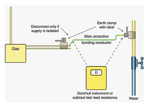 Figure
1. Continuity of main protective bonding conductors
Figure
1. Continuity of main protective bonding conductors
Remember to zero the
instrument first or, if this facility is not available, record the resistance
of the test leads so that this value can be subtracted from the test reading.
Important
Note:
If the installation is in
operation, never disconnect main bonding conductors unless the supply can be
isolated. Without isolation, persons and livestock are at risk of electric
shock.
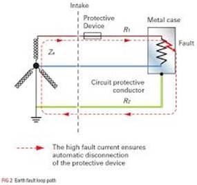
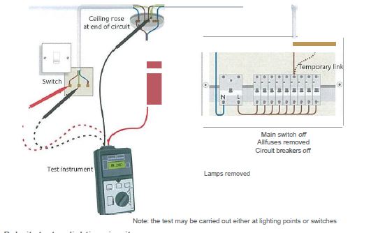
The continuity of circuit
protective conductors (CPCs) may be established in the same way, but a second
method is preferable, as the results of this second test indicate the value of
(R1+R2) for the circuit in question.
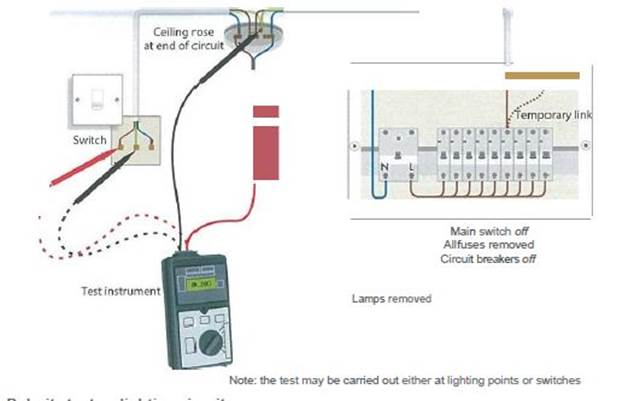
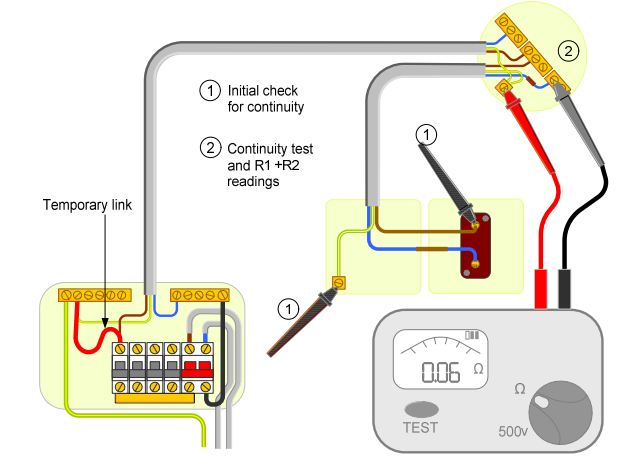
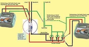
The test is conducted in
the following way (Figure 2):
- Temporarily link together the line
conductor and CPC of the circuit concerned in the distribution board or
consumer unit.
- Test between line and CPC at each outlet
in the circuit. A reading indicates continuity.
- Record the test result obtained at the
furthest point in the circuit. This value is (R1+R2) for the circuit.
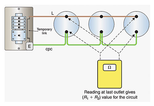 Figure
2. Circuit protective conductors (CPC) continuity
Figure
2. Circuit protective conductors (CPC) continuity
There may be some difficulty
in determining the (R1+R2) values of circuits in installations that comprise
steel conduit and trunking and/or steel wire armoured
(SWA) cables and mineral-insulated metal-sheathed (MIMS) cables because of the
parallel earth paths that are likely to exist.
In these cases, continuity
tests may have to be carried out at the installation stage before accessories
are connected or terminations made off as well as after completion.
Terminology
in Europe:
Supplementary
bonding. Green and yellow conductors that connect accessible metal parts
of electrical equipment (such as a heated towel rail) to accessible metal parts
of items of electrical equipment and/or accessible metal parts of items that
are not electrical (such as pipes). These connections are made to prevent a
dangerous voltage between two accessible metal parts, in case
there is a fault. You may need supplementary bonding for rooms containing a
bath or shower, except where all circuits in the room are RCD protected and the
main bonding is up to the required standard.
Residual
current devices (RCDs). A sensitive switching device that trips a circuit
when it finds an earth fault.
The
circuit protective conductor(increasingly called the ‘c.p.c.’) is a system of conductors joining together all exposed conductive
parts and connecting them to the main earthing terminal. Strictly speaking, the
term includes the earthing conductor as well as the equipotential bonding
conductors.
Video
https://www.youtube.com/watch?v=ScD3Y1Ty5n8
https://www.youtube.com/watch?v=R2XygQfgJao
https://www.youtube.com/watch?v=rnvNfI__kYU
https://www.youtube.com/watch?v=u5SCOb4dBus
https://www.youtube.com/watch?v=Ipo-veJdiTc
https://www.youtube.com/watch?v=2H8ATUWefSk
Continuity and Polarity of
Protective Earth
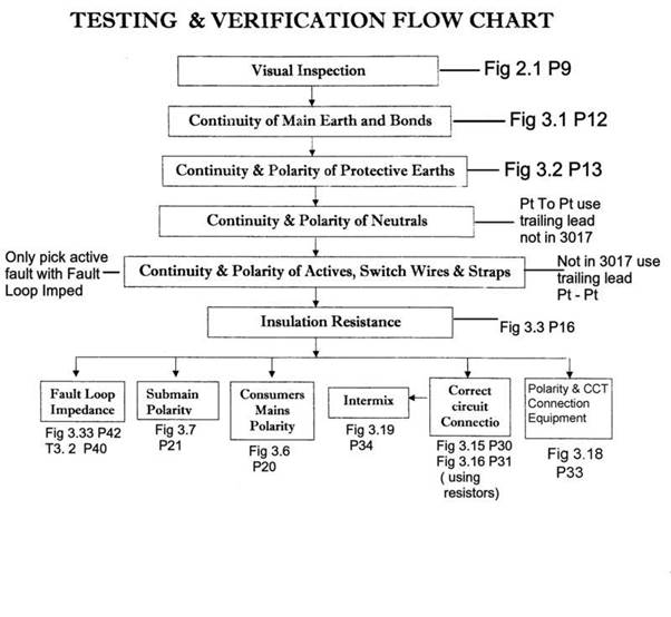
Testing requirements for an installation
When carrying out testing on a new installation or when
alterations/additions are made to an installation, a suggested sequence of
testing as per AS/NZS 3000:2018 Section 8 would
be as follows:
- Visual
inspection of works carried out
- Earth
resistance test – continuity of the main earthing conductor
- Earth
resistance test for other earthed and equipotential bonded parts
- Insulation
resistance test of installation
- Polarity
and connections test of circuits/wiring installed e.g.
consumers mains, submains or sub-circuits.
- Earth
fault loop impedence test
- Verification
of operation of residual current devices
Further information can be found under AS/NZS 3000:2018 Section 8:
Verification.
When carrying out testing ensure all test results are recorded and
records are maintained for 5 years. (ELR 1991 Reg 52
(2D)
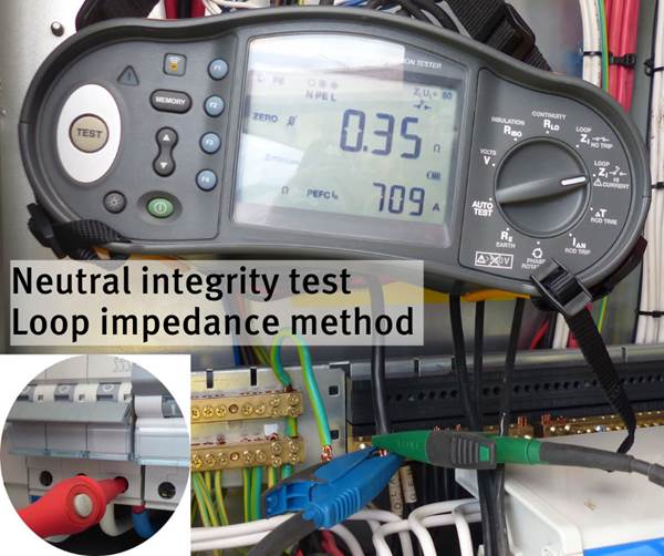
Recently during inspections being carried out it has been found that the
MEN connection has been missed during checking and testing on several installation
inspections. This is regarded as a serious defect. Reason given for this has
been that it is no longer a requirement to carry out earth fault loop impedence tests as circuits are now covered by RCD and the
test is no longer required.
Electrical contractors and electrical workers are reminded that while
RCDs can be used to achieve automatic disconnection of supply, RCDs fitted
to circuits are intended only to augment other measures of basic protection and
that RCD’s are additional circuit protection to that of the primary circuit
protection. (AS/NZS 3000:2018 clause 2.4.1, 2.6.1)
The operation of the circuit protection is reliant upon the integrity of
the MEN connection and the supply neutral (PEN) conductors. If the value of the
earth fault loop impedance exceeds that of Table 8.1 AS/NZS 3000:2018 then
correct operation of the primary circuit device may not be achieved. Further
information on this can be found under Appendix B, B4: Protection by automatic
disconnection of supply.
When completing the Electrical Safety Certificate and/or Notice of completion for electrical works carried out,
electrical contractors and workers are again reminded to ensure that when
completing section 4E as the completing electrical worker and signing off as
the nominee that all electrical work has been checked, tested, test results
recorded and certified safe to operate when connected to supply. (AS/NZS
3000:2018 clause 2.1.2 and 4.1.2, E(L)R 1991 Reg 49, 49B, 52(2B), 52(2D) and
52B.)
Note: Under certain circumstances a test for fault loop impedance could
give a false impression that a MEN is present, therefore a visual confirmation
of the MEN is essential.
Video
https://www.youtube.com/watch?v=LcJu2tlhpiI
https://www.youtube.com/watch?v=vtyPt9MVUbA
https://www.youtube.com/watch?v=dMtxkhL6c8I
https://www.youtube.com/watch?v=X5VEtGTSrwg
Continuity and polarity of
active switch wire and Straps
What is polarity testing?
Polarity testing is one of the tests that are required for
initial testing of the installation under IEC 60364 standard.
This test
will verify that all the switches installed in the system are connected in
current carrying conductor and not in neutral. For example, if you isolate
or switch the neutral of a circuit via a single-pole circuit breaker or switch,
it would appear that the circuit is dead where in fact
it is still live.
|
source: TLC-Direct UK |
If polarity is not correctly determined there may be a risk of electric
shock during maintenance procedures.
This would not be the case, as live conductors and connections
would be present at fixed equipment, sockets and
switches - this would be very dangerous.
There are three recognized methods of
evaluation. All three methods have their advantages and possible dangers, if they are not carried out correctly.
Methods of polarity testing
1. Polarity by visual inspection
By using your knowledge and sight, correct termination of cables relating to
core colors can be established.
|
|
|
Color Coding Sample |

It is essential that polarity is checked visually during the
process of installation, especially in cases where checking by testing is
impractical.
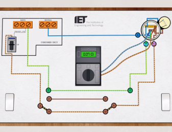
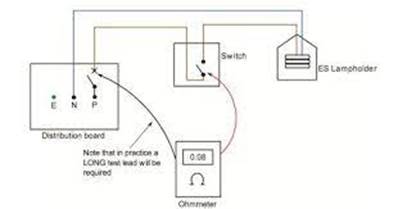
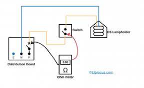
2. Polarity by continuity testing
If visual inspection is not possible, you will need to use a
low-resistance ohmmeter for this test. When you
continuity test radial and ring final circuits, part of the process is to test
and visually inspect the polarity of fixed equipment and socket outlets.
|
|
|
Polarity testing using low resistance ohmmeter |
Steps:
- Switch off the circuit breaker supplying
the circuit.
- From the specific circuit, put a temporary
link that will connect the line conductor and the CPC or any equipotential
bonding conductors. It will serve as a testing point for convenience
- Conduct continuity testing by placing the
test leads across the line conductor and the nearest
CPC or any exposed conductive parts of the circuit.
- If the instrument shows zero reading (with
continuity sound) then the switch is connected properly to the line
conductor.
- If the instrument shows some significant
ohmic value then the switch is not connected to
the line conductor. Interchange the connections to fix the problem.
3. Live testing for polarity
If the two methods are not possible due to urgency we can
perform live polarity testing by using the approved voltage GS38.
Steps:
1. Test between LINE and NEUTRAL terminals

2. Test between LINE and EARTH terminals.

3. Test between NEUTRAL and EARTH terminals

The test instrument should indicate full voltage (230V) between Line-Neutral and Line-Earth
conductors. No voltage should be detected between Neutral-Earth.
Source:
- City and Guilds
- BS 7671
- TLC Direct
Testing & the Six ‘Mandatory’ tests
March 21, 2017Training8 Comments
 Author:
Harry Dreger, NECA Education & Careers LEA & LEI Teacher
Author:
Harry Dreger, NECA Education & Careers LEA & LEI Teacher
The Wiring Rules require that we perform these
tests on low voltage installations before they are connected to Supply. But do
they REALLY matter? Will it REALLY affect an installation? Aren’t they a waste
of time? Many electricians feel they are, and it’s not worth their time.
So
are they important? YES!! Why?? To ensure the correct and safe (ongoing)
operation of an electrical installation. That is their purpose, and this is
what it’s about:
1. Test the continuity of the earthing system. Put simply this ensures that an ‘earth’ exists and it is suitable to ensure the fuse/circuit breaker
will operate before a piece of ‘faulty’ equipment becomes ‘live’, potentially
killing somebody.
2. Insulation resistance. If this is too low, we risk equipment
inadvertently becoming ‘live’, fires and overheating from ‘leakage currents’,
and ‘equipment damage’ (particularly with electronics in equipment today.
3. Polarity. To
ensure ACTIVE (A), NEUTRAL (N) and EARTH (E) wires are in the right position.
Does that matter? Yes! I.e. swap A and E and risk
livening the frame of a piece of equipment and somebody can die. Or, put the
earth wire in the wrong place and it will carry load current, melt and cause a fire. (Remember, the earth wire is often
smaller than the A and N.)
4. Correct Circuit connections. Ensures that circuits are not suitably
connected in such a way that may cause safety hazards or incorrect operation. I.e. A piece of equipment being inadvertently connected to
two (2) sources of supply is potentially life threatening to an electrician
working on the circuit.
5. Fault loop Impedance. (This is associated closely with voltage
drop). The Wiring Rules mandate that under fault, a maximum voltage of 50 V can
exist on a piece of equipment for no longer than 0.4 seconds before the circuit
protection operates (see touch voltage). If the fault loop impedance is
incorrect, this will not happen.
6. Operation of R.C.D.s. Under the wiring rules, R.C.D.s are
(currently) only required to be fitted to certain circuits where it has been
deemed that safety is ‘more than normally’ likely to be a concern, i.e. kids sticking a fork in the toaster or socket outlet
etc. For that reason it is crucial to ensure the
R.C.D.s installed actually operate.
Video
https://www.youtube.com/watch?v=LcJu2tlhpiI
https://www.youtube.com/watch?v=ScD3Y1Ty5n8
https://www.youtube.com/watch?v=ZQuwbnyxPaY
https://www.youtube.com/watch?v=P-D6chUrRNk
https://www.youtube.com/watch?v=lmEnAYFSuzs
https://www.youtube.com/watch?v=xH5FxehSpM4
https://waypointinspection.com/what-is-reverse-polarity/
Insulation Resistance
What is insulation
resistance test?
An insulation
resistance (IR) test measures the total resistance between any two
points separated by electrical insulation. The test, therefore, determines
how effective the dielectric (insulation) is in resisting the flow of
electrical current.
What is the minimum
acceptable value of insulation resistance?
Insulation
resistance should be approximately one megohm for each 1,000 volts of
operating voltage, with a minimum value of one megohm.
Video
https://www.youtube.com/watch?v=TdeU6UCCfTY
https://www.youtube.com/watch?v=Ek1u2RjQffU
https://www.youtube.com/watch?v=FV0QavM9sN8
https://www.youtube.com/watch?v=yY8nsGn2xBo
https://www.youtube.com/watch?v=wxSL6oDkhGU
https://www.youtube.com/watch?v=_-n6BiFJy8w
https://www.youtube.com/watch?v=2_zHb0QvlUg
https://www.youtube.com/watch?v=eRE_8njFxZs
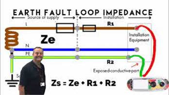
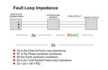
Fault Loop Impedance
What is a fault
loop impedance test?
Loop testing
demystified. ... The main reason for earth loop impedance testing – which is
often simply called loop testing – is to verify that, if a fault occurs
in an electrical installation, sufficient current will flow to operate the fuse
or circuit breaker protecting the faulty circuit within a predetermined time.၂၀၁၅- အောက် ၁
https://www.youtube.com/watch?v=_twVvsGo81A
https://www.youtube.com/watch?v=F3rw1KwFboQ
https://www.youtube.com/watch?v=d6AI_RNTTdw
https://www.youtube.com/watch?v=Ax1MzklVtI0
Submain Polarity
Testing for correct polarity
Several installations have been identified where
either people at the property, or at another property, have received electric
shocks due to incorrect polarity of consumer mains or submains.
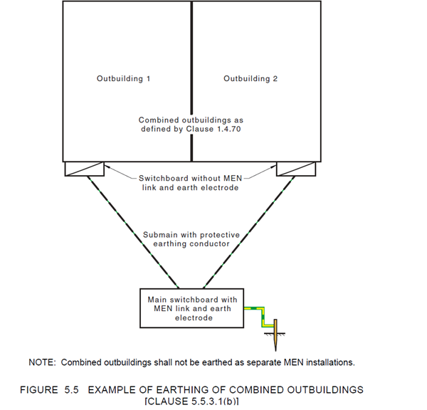
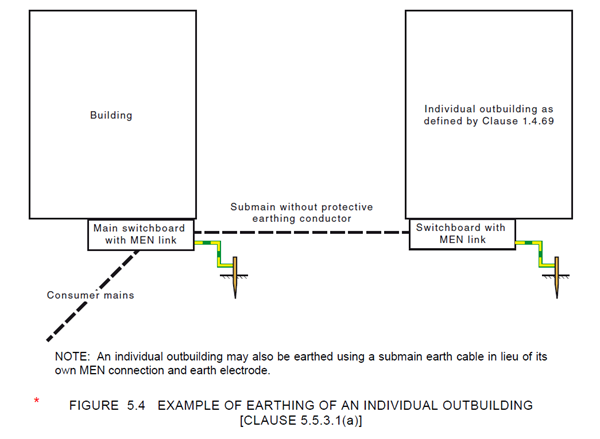
Incorrect polarity connections on consumer mains or
submains supplying an outbuilding with a separate multiple earth neutral (MEN),
will result in an energised earthing system.
Testing will ensure any incorrect connection is
identified and rectified, to prevent the risk of electric shock.
The protective earth neutral (PEN) is the most
important earthing conductor in an electrical installation. The impedance of
the PEN must be low enough to pass the current necessary to operate the
overcurrent protective device and be consistent with the length, cross
sectional area and type of conductor material.
Correct polarity testing for low voltage
connections to an electricity network or where an electrical installation in an
outbuilding has a separate MEN connection in accordance with AS/NZS 3000:2018,
Clause 5.5.3.1(c) must:
- include
a visual inspection
- ensure
the use of suitably designed and correctly rated test equipment
- ensure
an effective independent earth is used
- ensure
that any neutral bonding conductor (i.e.to raiser bracket) is disconnected
- prove
the operation of the test equipment before and after testing
- prove
the identity of the incoming active conductors
- prove
the identity of the incoming neutral conductor
- prove
the integrity of the supply neutral and connections
- confirm
phase rotation
- ensure
that any bonding conductor removed for testing is tested and reconnected
- ensure
that all conductors are correctly connected, including the MEN connection
- ensure
a final visual and verification of correct connections is completed.
For detailed information and guidance on conducting
a polarity test for supply to electrical installations and neutral integrity
tests for supply to electrical installations, refer to AS 4741 (Testing of
connections to low voltage electricity networks).
Remember, polarity testers which are connected to a
final subcircuit do not confirm mains polarity and will indicate that polarity
is correct even if there is a reverse polarity.

Mains polarity verification testing
6 December 2018
We’ve added two new
how-to infographics to the Electrical Workers Toolbox that demonstrate safety
verification polarity tests with the use of an independent earth probe.
The Multiple Earth
Neutral (MEN) system we have in New Zealand is only safe if the polarities of
both the supply system and the installation are correct and the connections of
the neutral conductor are reliable.
The wiring rules AS/NZS
3000.2007 list the compulsory electrical tests required to be carried out on an
installation, one of which is polarity testing on mains and submains.
Transposed conductors in
the consumer mains or a disconnected main neutral to an electrical installation
can create significant risks of shock or electrocution, and property damage
through overheating and fire.
Polarity testing is absolutely critical and therefore must be independently
verified by the installer, inspector, and person making a connection to an
electricity supply.
The underlying principle
of mains polarity testing is to carry out all the necessary tests and checks
that will ensure the phase and neutral conductors are not transposed, and that
the neutral is continuous and earthed.
Never liven mains to
carry out live polarity testing unless correct polarity has first been proven.
Failure to do so can create an immediate and serious risk of electrocution,
shock, or fire should the mains conductors be transposed. The safety
verification polarity test is only to be carried out after correct polarity was
previously established.
These tests and other
practical guidance have been provided to assist electrical practitioners to
achieve safe, compliant and competent electrical work,
and to promote continued improvements in those areas.
Guidance on mains
polarity testing is provided in standard AS/NZS 3017:2007 Electrical
Installations – Verification Guidelines. This standard is freely available to
all licensed practitioners through a RealMe login
from the EWRB
homepage.

Consumer Main Polarity
TESTING
FOR REVERSED POLARITY
BY PAUL SKELTON
28/06/2011
In the last edition of Electrical Connection we
ran an article highlighting the growing number of reported reverse polarity
incidents in Victoria in the past year, particularly surrounding the
installation of new metering equipment.
While the danger is very
real, and the number of incidents is assuredly growing, it turns out that the
information we were presented isn’t relevant to the vast majority (99.9%) of
Australian installations.
Institute of Electrical Inspectors
life member and former Electrical
Connection contributor George Bosomworth says: “The test
described does not prove what is claimed when applied in Australia or New
Zealand (i.e. where the system of distribution used is
our multiple earth neutral, MEN, system).”
The test described is only
valid where the MEN connection is upstream of the reversal of polarity, he
says.
“In the US there are many
situations where this test would be valid – but not so in Australia or New
Zealand.
“To put it simply, if the
neutral and earth (US ‘ground’) are connected together
downstream of the meter (as is the case for our MEN system) and the active (US
‘hot’) is transposed for the neutral upstream of that point, both the neutral
and earthing conductors within the installation will be at the same
(active/hot) potential.
“Therefore, testing voltages between
the pins of an outlet (US receptacle) will indicate identical values whether
the polarity is reversed or not and the fault will not be detected (i.e. with supply at correct polarity; A – N = 230V, A – E =
230V, N – E =~0V. Polarity reversed upstream of MEN connection; N – A = 230V, N
– A = 230V, A – A =~0V.)
“For a test at an outlet to
be valid in Australia/NZ, the reference point for testing must be an
independent connection to mother earth (the soil) at a point clear of any
material that could be connected electrically to the installation, such as
underground water piping, etc. Typically a large
screwdriver shaft driven into the soil may be used.”
This leads to the next point
that often arises in such a discussion, he says: “Reliance on the main earth.”
“Many would say that the main
earth will cause a fuse to blow. This would rarely be the case.
“Typical earth resistances
for single electrodes driven 1.2m deep are in the range of 50Ω to
100Ω (or more). If we apply the nominal 230V to such a resistance Ohm’s
Law dictates that the current flow will be in the range of 2A to 5A. Even if
the earth resistance is lowered to 10Ω the current will only be 23A.
Hence, relying on the main earth to operate protection is a fallacy.”
A further issue arising from
all of this is the MEN system itself.
“When that system of
distribution was adopted, the reticulated water system consisted of metallic
piping that, when used as the main earthing system, acted as a backup to the
supply neutral conductor.
“With the advent of
non-conductive water reticulation and the use of single earth electrodes there
is now no back up for the supply neutral and hence the rise in neutral related
problems such as shocks.
“It may be that this system
of distribution needs to be reviewed.
“The requirement to earth the
neutral at each installation arises from the need to keep the supply neutral as
close to true ground potential as practicable. (If there was no such connection
the voltage between ground and the supply neutral would be about half that of
the voltage drop along the length of the distribution circuit – think about
it).”
Thus this
requirement more correctly sits with the distributor.
“If
this were to be the case, an RCD with a tripping current in the order of 300 –
400mA used as a main switch would protect the customer’s installation in the
event of a supply neutral failure.”
How do you conduct
a polarity test?
The Polarity Test
sequence:
- Select a GS 38 approved
voltage indicator and locate the Main Switch. Test between Line and
Neutral terminals.
- Test between Line and Earth
terminals.
- Test between Neutral and Earth terminals.
Video
https://www.youtube.com/watch?v=PtmqaolzPL0
https://www.youtube.com/watch?v=I8FH9iTr-vs
https://www.youtube.com/watch?v=IS-C5hwJ-tI
https://www.youtube.com/watch?v=I8FH9iTr-vs
https://www.youtube.com/watch?v=X5VEtGTSrwg
Intermix Circuit
https://www.youtube.com/watch?v=AZenZfLQQgw
Safe isolation
The procedure
for proving dead should be by use of a test lamp or two pole voltage detector as recommended in HSE Guidance Note GS38.
Non-contact voltage indicators (voltage sticks) and multi-meters should not be
used. The test instrument should be proved to be working on a known live source
or proprietary proving unit before and after use. All phases of the supply and
the neutral should be tested and proved dead.
Test sequence
and descriptions
The following
tests are carried out with the Consumers main switch isolated
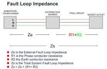
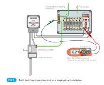
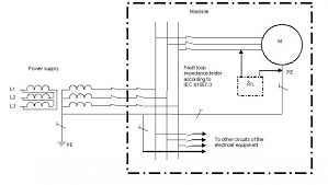
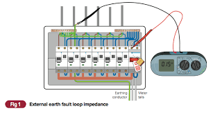
1. Extenal earth fault loop impedance
Reason: To
establish that a good earth exists at the installation in
order for the remaining tests to go ahead.
Method:
Disconnect the main earthing conductor from the main earthing terminal. An
earth fault loop impedance tester is connected at line and earth (main earthing
conductor) at the supply side of the installation and a test performed.
Reconnect the main earthing conductor. The result is Ze and recorded on the
sheet. The prospective fault current is measured at the same time after the
reconnection of the main earthing conductor.
2. Continuity
of protective and bonding conductors
Reason: To
check that all circuit protective conductors (green and yellow cables) are
continuous and are present at every electrical accessory on the circuit. Also to check that the main earthing conductor and main
bonding conductors are continuous and correctly connected.
Method 1: The
line conductor is connected to the circuit protective conductor of the same
circuit at the consumer unit and a measurement taken at ALL accesories
on that circuit between line and c.p.c. The highest
measurement obtained is recorded on the test report.
Test result is R1 + R2. The line conductor and neutral conductor are then
connected and the above repeated to obtain R1 + Rn
Method 2 (used
for main earth and main bonding conductors): A wandering lead is connected to
one end of the conductor to be tested and a measurement taken between the other
end of this lead and the other end of the conductor.
Test result is R2.
During this test polarity can be checked as well. The continuity of the neutral
conductor can also be checked.
3. Continuity
of ring final circuit conductors
Reason: This
test ensures that all ring final circuits (sockets usually) are indeed a
continuous ring with no interconnects or breaks within it.
Method: The
line, neutral and earth conductors of the circuit are identified and a
measurement from one end to the other end of each is taken. These results are
r1, r2 and rn.
The incoming line conductor is then connected to the outgoing earth conductor
and the outgoing line conductor is connected to the incoming earth conductor. A
measurement is then taken at ALL socket outlets on the ring. The highest of
which is recorded on the report.
This result is R1+R2 for that circuit. The above is then repeated using the
neutral conductor instead of the earth conductor. This test provides R1+Rn
which does not need to be recorded on the report but is essential to check the
circuit correctly.
4. Insulation
Resistance
Reason: This
test checks whether the insulation around a cable is still intact and has not
broken down over time. It is a good indicator of the age of an installation.
Method: An
insulation resistance tester is connected across line and neutral tails at the
origin of the supply. 500V are then pumped down the conductors to see if any
voltage leaks across from one conductor to the other. The same is then done for
the line and earth and the earth and neutral conductors.
5. Polarity
Reason: To
check that all accesories are correctly connected to
line, neutral and earth and that all switches and circuit breakers are
connected in the line conductor only.
Method: The method
for this is the same as for continuity and is usually done at the same time by
operating switches etc whilst conducting the test.
6. Earth
electrode resistance
Reason: To make
sure that any earth electrode used is of a sufficiently low impedance to allow
the timely operation of the RCD protecting the installation.
Method: An
earth fault loop impedance tester is connected between line and earth at the
origin of the supply and a test performed. The result of which is considered
the resistance of the electrode (Ra).
The following
tests are carried out with the Consumers main switch energised
7. Live
polarity test
Reason: To
verify polarity of supply authorities system.
Method: An
approved voltage indicator shall be used or test lamp to GS38. Using the
approved voltage indicator, one probe shall be placed on the incoming neutral,
and the other on the incoming line conductor, on the main breaker. The
indicator should show it is live. One probe shall now be placed on the CPC and
the other on the incoming line conductor. The indicator should show it is live.
A test shall be preformed between CPC & incoming
neutral. The indicator should show that it is not live.
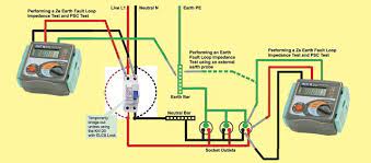
8. Earth fault
loop impedance
Reason: This
test is done at the furthest point on a circuit in order to make sure the
impedance of the earth path is not too high even at the furthest point so that
sufficient current will flow under fault conditions to take out the circuit
breaker protecting the circuit.
Method: An
earth fault loop impedance tester is connected to line and earth at the
furthest point on the circuit and the test performed.
9. RCD test
Reason: To make
sure RCD's trip within the correct time
Method: An RCD
tester is connected and a test at 1/2 times, 1 times
and 5 times the trip current is performed on each side of the cycle and a time
of trip obtained. Usually milli-seconds with the highest being recorded. The
manual test button is then pressed.
10. Functional
testing
Reason: To make
sure all switches, isolators, MCB's etc. work as they should.
Method. Self explanatory.
Correct Circuit
Connection
Electrical polarity (positive and negative) is the
direction of current flow in an electrical circuit. Current flows from the
positive pole (terminal) to the negative pole. ... In the context of
electricity installations, a polarity test is used to confirm the correct
connection of the line and neutral conductors.
UEEEL0039
|
2.Select wiring systems, cables, control and protection for general electrical
installations |
|
G063+G107 |
http://www.highlightcomputer.com/electricaltrade2021.htm#G063
http://www.highlightcomputer.com/electricaltrade2021.htm#G107
3.Install low voltage (LV) wiring and
associated accessories
G103+G104
http://www.highlightcomputer.com/electricaltrade2021.htm#G103
http://www.highlightcomputer.com/electricaltrade2021.htm#G104
4.Install and connect LV appliances, switchgear and associated accessories
G063+G033
http://www.highlightcomputer.com/electricaltrade2021.htm#G063
http://www.highlightcomputer.com/electricaltrade2021.htm#G033
Capstone Test Questions
Capstone_Practical_Tutorial_Questions
Capstone
Practical Test Question Version 4
Capstone
Practical Test Question Version 5
REFERENCE NOTES
ACA-Testing-electrical-installations-Final-2014
crn-sc-010-inspection-and-testing-procedures-v11-apl-2016
Protection_Methods_Week_2_G063A_V1.4
VESI-Installation-Supply-Connection-Tests-and-Procedures-June-2017